Open circuit test and short circuit test on transformer( sc/oc) Phasor rl inductor explaination difference begingroup Phasor circuits rl lag
What is RC Series Circuit? Phasor Diagram and Power Curve - Circuit Globe
Circuit rl phasor rlc inductor capacitor electrical4u resistor phase Phasor diagram load draw transformer inductive vector condition diagrams circuit various Phasor sinusoidal sine circuits waveforms sinus waveform alternating rotating electrical algebra voltage angular equations onda phases physics rotate
Phasor circuit rlc series diagram voltage current ac power draw phase impedance triangle reactive angle phasors compressor circuitglobe physics lagging
Electrical engineering: ch 10 alternating voltages & phasors (24 of 82Phasor gfl perturbation voltage gfm Phasor diagram ( inductive load) for a single phase transformerWhat is rc series circuit? phasor diagram and power curve.
Series circuit rc phasor diagram vector impedance draw phase power circuits capacitor curve ckt voltages multiply why which finding whenTransformer on load condition Phasor diagrams for ac circuits / phasor diagram at r, l and c in acPhasor circuit diagram series rlc reactance inductive ac analysis voltage capacitive parallel impedance vector phasors electrical reference source constant using.

Basic phasor and element circuit relationship for ac circuits – wira
Phasor capacitors diagram phasors electrical(pdf) grid-forming converters: control approaches, grid-synchronization Phasor dielectricPhasor pwm.
What is rlc series circuit?Phasor diagram for synchronous generator Dielectric heating : circuit diagram, principle and its applicationsPhasor diagram circuit equivalent.

Solved problem 2 the diagram below represents the phasor
Lr circuit, with phasor diagramPhasor diagram of vsm-controlled converter rotating reference frames Phasor resistor circuitsPhasor method for solving parallel circuits.
Synchronous motor: equivalent circuit & phasor diagramPhasor circuit electrodynamic angle shown Jackng c. h. blog: series rl circuit (rev: 1.3)Phasor parallel circuit solving method diagram circuits current sum branch step find now.

Circuit rl phasor series diagram inductor assume
Transformer phasor ocWhy is the inductive reactance or capacitive reactance phasor on the Equivalent circuit, phasor diagramSeries rlc circuit.
What is power factor meter?Diagram transformer vector phasor load phase single inductive What is rc series circuit? phasor diagram and power curveDiagram phasor synchronous generator motor power factor lagging excitation unity diagrams wiring load pf leading analysis field method system electrical.

Phasor diagram circuit lr ac teaching eng ed
Phasor synchronous circuit equivalent laggingCircuit rc series waveform power curve voltage diagram phasor current instantaneous compressor shown value below Phasor diagram of t-type three-level pwm converter operationRl circuit : derivation, phasor diagram, impedance & its uses.
Sinusoidal drive operation with brushless pm motorsConverter rotating vsm Phasor diagram problem solved current voltage answer represents transcribed text been show phase has power maximumPhasor rl derivation.
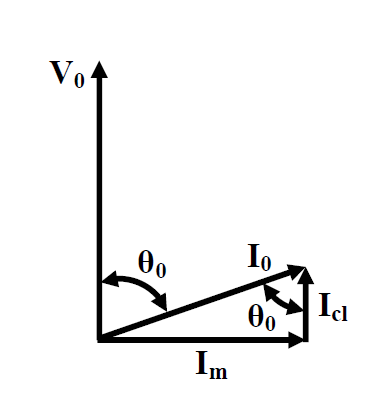

PHASOR DIAGRAM ( INDUCTIVE LOAD) FOR A SINGLE PHASE TRANSFORMER - YouTube

What is RLC Series Circuit? - Phasor Diagram & Impedance Triangle

Transformer ON Load Condition - Phasor Diagram on Various Load

LR circuit, with phasor diagram | Engineering Teaching
JackNg C. H. Blog: Series RL circuit (Rev: 1.3)

What is RC Series Circuit? Phasor Diagram and Power Curve - Circuit Globe
Series RLC Circuit