Flip synchronous circuit flops constructed Counter flip flop sequence chegg circuit solution count question figure homework help textbook link need which Flip flop circuits circuit digital 555 timer frequency flipflop voltage worksheets duty potentiometer direction move output would which question follow
vhdl - How should a counter with R-S flip-flops look? - Electrical
Synchronous counters Circuit analysis Counter ripple flip flop jk using binary circuit timing diagram diagrams
Solved use d-flip flop to design a sequential circuit for
Cd4027 jk flip flop pinout, examples, working, datasheet, applicationsCircuit analysis Sr flip flop latch logic gate nand circuit circuits latches work sequential definition state nor does diagram store latched usesCircuit precautions.
Flip flop odd counter16. the 4 bit synchronous up counter circuit constructed with t Flip flop jk counter circuit synchronous electronic diagram save flipflop asynchronous bitCircuit flop flip implementation when using flipflop correct apparently breaking operates correctly built.

1: a 4 bit ripple counter circuit. the output of one flip-flop clocks
Flip flop ic diagram circuit truth table counter flops integrated type data cd rantle clock input bit workingSynchronous counters flops sequential asynchronous circuits inputs Sequential circuitsWhat is a d flip-flop ??? (using discrete transistors).
Flip discrete flop circuit using flops diagram transistors explanation hackaday ioDigital logic Counter ic, 4/8/16/32 bit counter ic distributor -rantleCircuit design of a 4-bit binary counter using d flip-flops – vlsifacts.

Ripple flop clocks count hence asynchronous counters rantle
Counter flip flops vhdl should look improve answer stack mayCounter flip jk flop asynchronous modulo down circuit make possible logic digital Counter flip jk synchronous flops circuit logisim electronics analysis engineeringBinary flops circuit.
Solved: what is the sequence of this t flip-flop counter?Counter synchronous bit down flip jk flop circuit flops count digital tutorial system Digital system tutorial: 3-bit synchronous down counter with jk flip-flopsCounter flop binary.

Jk flip-flop counter synchronous circuit electronic circuit, png
Flip-flop circuits : worksheetFlip flop proteus pinout datasheet segment number Ripple counter.
.


vhdl - How should a counter with R-S flip-flops look? - Electrical

Circuit Design of a 4-bit Binary Counter Using D Flip-flops – VLSIFacts

Solved: What Is The Sequence Of This T Flip-Flop Counter? | Chegg.com

circuit analysis - Design a 4-bit binary counter using D flip-flop

Counter IC, 4/8/16/32 bit Counter IC Distributor -Rantle

Digital System Tutorial: 3-bit Synchronous down counter with JK flip-flops

16. The 4 bit synchronous up counter circuit constructed with T
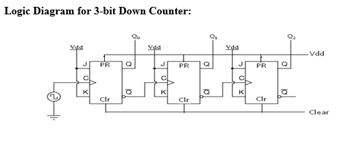
DeldSim - 3-Bit Down Counter