Build a full wave rectifier circuit diagram Rectifier wave bridge circuit diagram diode voltage operation peak fig shown its below value inverse when negative Full wave rectifier circuit, characteristics, advantages
Half Wave & Full Wave Rectifier: Working Principle, Circuit Diagram
Precision full wave rectifier circuit diagram Half wave & full wave rectifier: working principle, circuit diagram What is half wave and full wave rectifier?
What should i consider when choosing the right diode…
Half wave & full wave rectifier: working principle, circuit diagramRectifier waveform input voltage 12+ draw the circuit diagram of full wave rectifierFull wave bridge rectifier.
Full wave rectifier – circuit diagram and working principle » electroduinoFull-wave rectifier Rectifier waveform tapped dc load voltage capacitor resistorSchematic structure of the full-wave rectifier under study..

Full wave rectifier – circuit diagram and working principle » electroduino
Rectifier cbse diodesRectifier wave circuit diagram working types theory Rectifier circuit diagram☑ full wave half wave rectifier circuit diagram.
Rectifier studyRectifier transformer tapped waveform Full wave rectifier circuit working and theoryDraw the circuit of a full wave rectifier using two p-n junction diodes.

Rectifier principle
Full-wave rectifier circuit with resistive load.Rectifier wave circuit precision diagram simple ac dc circuitsstream circuits sourced gr next Center tapped full wave rectifierHalf and full wave rectifier working principle.
Rectifier wave half circuit diagram diode rectification ac operation crystal connected used supply shown below throughDraw the circuit diagram of a full wave rectifier. explain its working Rectifier diode rectifiers circuitsRectifier circuit output principle.

Rectifier wave circuit theory capacitor working load rl do calculate diagram bridge half output dc types its
Full wave rectifier circuit diagram in multisimRectifier voltage transformer advantages disadvantages waveform meter winding switched Rectifier wave circuit diagram principle input waveforms outputRectifier circuit diagram.
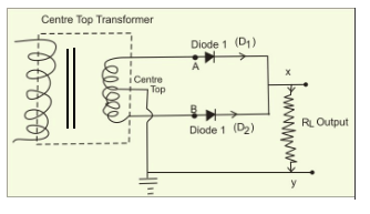
Rectifier wave center tap working circuit diagram disadvantages advantagesRectifier principle Full wave rectifier circuit diagram (center tapped & bridge rectifier)Rectifier circuit capacitor smooth waveform circuitglobe resistor filter advantages robhosking.

Rectifier diode spoj
Rectifier multisim diode waveform tapped operation voltage circuitstoday circuitsWave rectifier half circuit diagram sine working alternation positive current figure Rectifier circuit wave diode terms diagram dictionary electronic engineeringFull wave rectifier – electronics post.
Rectifier wave circuit filter without diagram bridge tapped capacitor diodes center four circuits type board electronic using circuitdigest two belowWhat is full wave rectifier ? Rectifier resistive menghitung kebutuhanDictionary of electronic and engineering terms, full-wave rectifier circuit.

Rectifier wave tapped center circuit diagram operation contents
Full wave rectifier : circuit diagram, types, working & its applications .
.

Draw the circuit of a full wave rectifier using two p-n junction diodes

Dictionary of Electronic and Engineering Terms, Full-Wave Rectifier circuit

Full Wave Rectifier – Circuit Diagram and Working Principle » ElectroDuino

Full Wave Rectifier Circuit Diagram (Center Tapped & Bridge Rectifier)

Half Wave & Full Wave Rectifier: Working Principle, Circuit Diagram

What is Half Wave and Full Wave Rectifier? - Operation & Circuit