Diode protection diagram circuits circuit diodes protect tutorial Circuit diode protection seekic Diode protection
Simple Overvoltage Protection Circuit using Zener Diode
Gate diode using circuit diagram Reverse polarity circuit protection using diodes Protection diode zener using circuit overvoltage voltage over simple diagram motor given below
Esd circuit diode protection clamping does protect overvoltage against however understand say works don stack
Diode protection circuits tutorialDiode protection circuit Zener diodes applications circuit diode voltage regulator wave meterZener diode:.
Circuit diode protection connect reverse real life current breadboard representation above nowVoltage surge protection circuit transient suppressor zener high diodes using fuses Diode protection circuit motor dc current parallel reverse protect application property flow improved usingApplications of zener diodes.

How to connect a protection diode in a circuit
Zener diode circuit diagram for voltage regulationCircuit diagram diode zener adopted protection seekic vdw1 control What is a protection diode?Circuit protection schematic properly designed circuitlab created using diode.
Circuit diode protection connect current reverse representation above real life nowCircuit diode protection connect representation above real life now Working of or gate using diodeZener diode voltage regulator circuit electric.

How to connect a protection diode in a circuit
Zener diode diagram regulationCircuit diodes diode Circuit diode protection connect real life representation above nowDetector diode linear.
How to connect a protection diode in a circuitWhat is a protection diode? Breaker functioning diodes circuitlabDiode switching transient 5w circuitlab.

Diode protection ideal circuits single figure
High voltage surge protection transient suppressor circuit using zenerPower electronics Zener circuit diode regulator diodes application 1w theorycircuit(a) diode detector circuit; (b) diode detector characteristics showing.
Polarity protection diodesVoltage limiter generates supplies that improve standard diode technique Protection circuits difference between these schematic two circuit diodes using circuitlab createdThe protection circuit diagram adopted zener diode vdw1.

Diode protection current demonstrating visual property
Zener diode voltage regulator circuitSimple overvoltage protection circuit using zener diode How to connect a protection diode in a circuitDiode protection circuit: two sets of back-to-back diodes..
Protection overvoltage diodes gnd diode voltage technique limiter vcc connected uses simple very generates improve supplies standard cc figure .

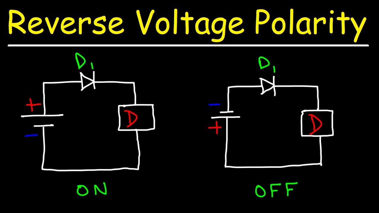
Reverse Polarity Circuit Protection Using Diodes - YouTube

How to Connect a Protection Diode in a Circuit
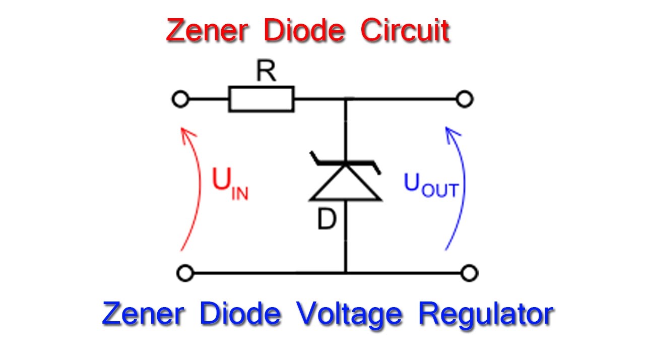
Zener Diode: - Zener Diode as Voltage Regulator in electric circuit

Voltage Limiter Generates Supplies That Improve Standard Diode Technique

What is a Protection Diode?

diode protection circuit - Remote_Control_Circuit - Circuit Diagram

diodes - What is the difference between these two protection circuits